- 您现在的位置:买卖IC网 > Sheet目录3872 > PIC16C57C-04/SP (Microchip Technology)IC MCU OTP 2KX12 28DIP
PIC18F2450/4450
DS39760A-page 166
Advance Information
2006 Microchip Technology Inc.
15.2.4
AUTO-WAKE-UP ON SYNC BREAK
CHARACTER
During Sleep mode, all clocks to the EUSART are
suspended. Therefore, the Baud Rate Generator is
inactive
and
proper
byte
reception
cannot
be
performed. The auto-wake-up feature allows the
controller to wake-up due to activity on the RX/DT line
while the EUSART is operating in Asynchronous mode.
The auto-wake-up feature is enabled by setting the
WUE bit (BAUDCON<1>). Once set, the typical receive
sequence on RX/DT is disabled and the EUSART
remains in an Idle state, monitoring for a wake-up event
independent of the CPU mode. A wake-up event
consists of a high-to-low transition on the RX/DT line.
(This coincides with the start of a Sync Break or a
Wake-up Signal character for the LIN protocol.)
Following a wake-up event, the module generates an
RCIF
interrupt.
The
interrupt
is
generated
synchronously to the Q clocks in normal operating
modes (Figure 15-8) and asynchronously if the device
is in Sleep mode (Figure 15-9). The interrupt condition
is cleared by reading the RCREG register.
The WUE bit is automatically cleared once a low-to-high
transition is observed on the RX line following the wake-
up event. At this point, the EUSART module is in Idle
mode and returns to normal operation. This signals to
the user that the Sync Break event is over.
15.2.4.1
Special Considerations Using
Auto-Wake-up
Since auto-wake-up functions by sensing rising edge
transitions on RX/DT, information with any state
changes before the Stop bit may signal a false End-of-
Character and cause data or framing errors. To work
properly,
therefore,
the
initial
character
in
the
transmission must be all ‘0’s. This can be 00h (8 bytes)
for standard RS-232 devices or 000h (12 bits) for LIN
bus.
Oscillator start-up time must also be considered,
especially in applications using oscillators with longer
start-up intervals (i.e., XT or HS mode). The Sync
Break (or Wake-up Signal) character must be of
sufficient length and be followed by a sufficient interval
to allow enough time for the selected oscillator to start
and provide proper initialization of the EUSART.
15.2.4.2
Special Considerations Using
the WUE Bit
The timing of WUE and RCIF events may cause some
confusion when it comes to determining the validity of
received data. As noted, setting the WUE bit places the
EUSART in an Idle mode. The wake-up event causes
a receive interrupt by setting the RCIF bit. The WUE bit
is cleared after this when a rising edge is seen on RX/
DT. The interrupt condition is then cleared by reading
the RCREG register. Ordinarily, the data in RCREG will
be dummy data and should be discarded.
The fact that the WUE bit has been cleared (or is still
set) and the RCIF flag is set should not be used as an
indicator of the integrity of the data in RCREG. Users
should consider implementing a parallel method in
firmware to verify received data integrity.
To assure that no actual data is lost, check the RCIDL
bit to verify that a receive operation is not in process. If
a receive operation is not occurring, the WUE bit may
then be set just prior to entering the Sleep mode.
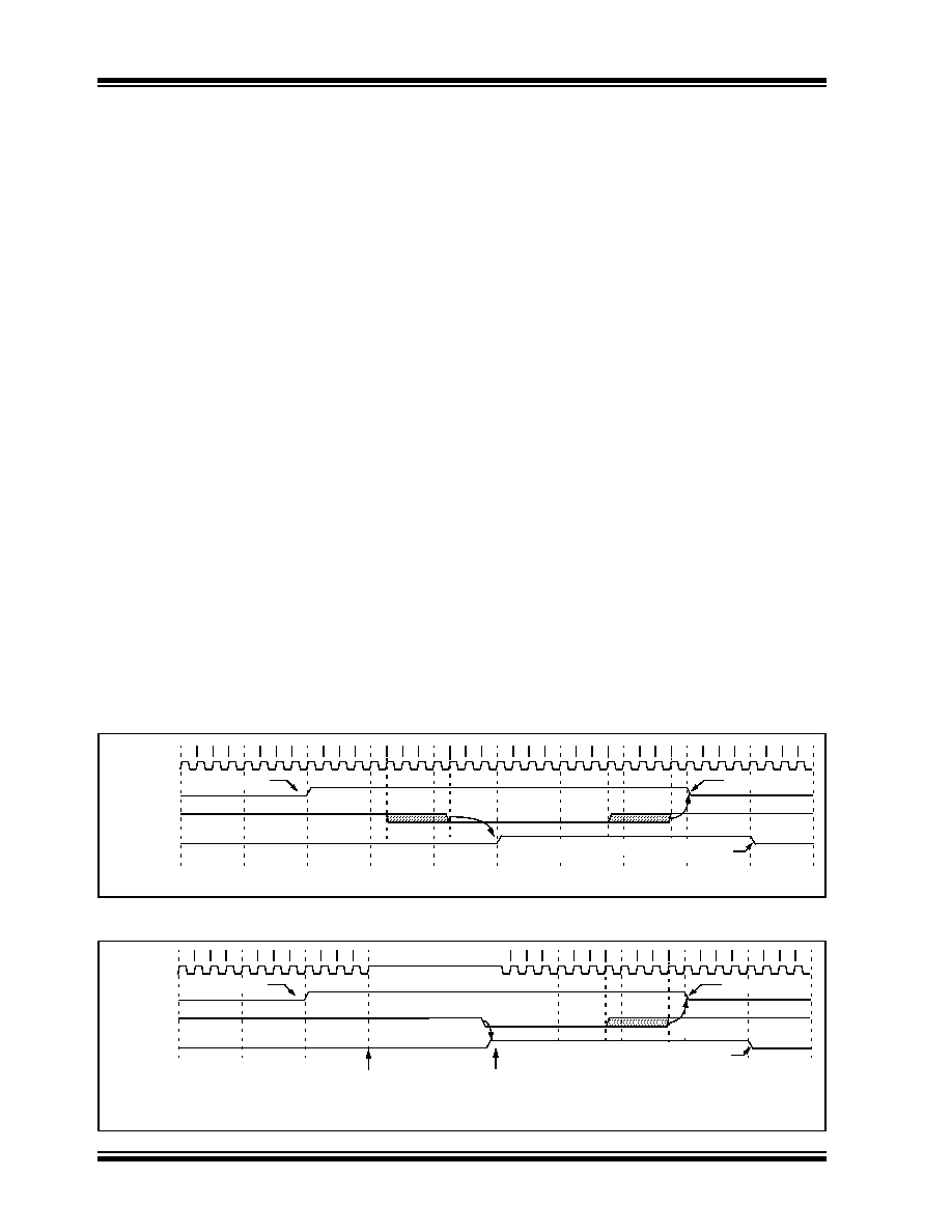
FIGURE 15-8:
AUTO-WAKE-UP BIT (WUE) TIMINGS DURING NORMAL OPERATION
FIGURE 15-9:
AUTO-WAKE-UP BIT (WUE) TIMINGS DURING SLEEP
Q1 Q2 Q3 Q4 Q1 Q2 Q3 Q4 Q1 Q2 Q3 Q4 Q1 Q2 Q3 Q4 Q1 Q2 Q3 Q4 Q1 Q2 Q3 Q4 Q1 Q2 Q3 Q4 Q1 Q2 Q3 Q4 Q1 Q2 Q3 Q4 Q1 Q2 Q3 Q4
OSC1
WUE bit(1)
RX/DT Line
RCIF
Note 1: The EUSART remains in Idle while the WUE bit is set.
Bit set by user
Auto-Cleared
Cleared due to user read of RCREG
Q1 Q2 Q3 Q4 Q1 Q2 Q3 Q4 Q1 Q2 Q3 Q4
Q1
Q2 Q3 Q4 Q1 Q2 Q3 Q4 Q1 Q2 Q3 Q4 Q1 Q2 Q3 Q4 Q1 Q2 Q3 Q4
OSC1
WUE bit(2)
RX/DT Line
RCIF
Sleep Command Executed
Note 1:
If the wake-up event requires long oscillator warm-up time, the auto-clear of the WUE bit can occur while the
stposc signal is still active.
This sequence should not depend on the presence of Q clocks.
2:
The EUSART remains in Idle while the WUE bit is set.
Sleep Ends
Auto-Cleared
Note 1
Cleared due to user read of RCREG
Bit set by user
发布紧急采购,3分钟左右您将得到回复。
相关PDF资料
PIC16LF628A-I/SO
IC MCU FLASH 2KX14 EEPROM 18SOIC
PIC16C55A-20/SO
IC MCU OTP 512X12 28SOIC
PIC24F16KA101-I/MQ
IC PIC MCU FLASH 16KB 20-QFN
PIC16F627-04/SO
IC MCU FLASH 1KX14 COMP 18SOIC
PIC16C58B-20I/P
IC MCU OTP 2KX12 18DIP
PIC24FJ16GA002-I/SS
IC PIC MCU FLASH 16K 28-SSOP
PIC16C55A-04I/SO
IC MCU OTP 512X12 28SOIC
PIC16CR77-I/ML
IC PIC MCU 8KX14 44QFN
相关代理商/技术参数
PIC16C57C-04/SP
制造商:Microchip Technology Inc 功能描述:IC 8BIT CMOS MCU 16C57 SDIL28
PIC16C57C-04/SP
制造商:Microchip Technology Inc 功能描述:Microcontroller IC Number of I/Os:20
PIC16C57C-04/SS
功能描述:8位微控制器 -MCU 3KB 72 RAM 20 I/O RoHS:否 制造商:Silicon Labs 核心:8051 处理器系列:C8051F39x 数据总线宽度:8 bit 最大时钟频率:50 MHz 程序存储器大小:16 KB 数据 RAM 大小:1 KB 片上 ADC:Yes 工作电源电压:1.8 V to 3.6 V 工作温度范围:- 40 C to + 105 C 封装 / 箱体:QFN-20 安装风格:SMD/SMT
PIC16C57C-04E/P
功能描述:8位微控制器 -MCU 3KB 72 RAM 20 I/O RoHS:否 制造商:Silicon Labs 核心:8051 处理器系列:C8051F39x 数据总线宽度:8 bit 最大时钟频率:50 MHz 程序存储器大小:16 KB 数据 RAM 大小:1 KB 片上 ADC:Yes 工作电源电压:1.8 V to 3.6 V 工作温度范围:- 40 C to + 105 C 封装 / 箱体:QFN-20 安装风格:SMD/SMT
PIC16C57C-04E/SO
功能描述:8位微控制器 -MCU 3KB 72 RAM 20 I/O RoHS:否 制造商:Silicon Labs 核心:8051 处理器系列:C8051F39x 数据总线宽度:8 bit 最大时钟频率:50 MHz 程序存储器大小:16 KB 数据 RAM 大小:1 KB 片上 ADC:Yes 工作电源电压:1.8 V to 3.6 V 工作温度范围:- 40 C to + 105 C 封装 / 箱体:QFN-20 安装风格:SMD/SMT
PIC16C57C-04E/SP
功能描述:8位微控制器 -MCU 3KB 72 RAM 20 I/O RoHS:否 制造商:Silicon Labs 核心:8051 处理器系列:C8051F39x 数据总线宽度:8 bit 最大时钟频率:50 MHz 程序存储器大小:16 KB 数据 RAM 大小:1 KB 片上 ADC:Yes 工作电源电压:1.8 V to 3.6 V 工作温度范围:- 40 C to + 105 C 封装 / 箱体:QFN-20 安装风格:SMD/SMT
PIC16C57C-04E/SS
功能描述:8位微控制器 -MCU 3KB 72 RAM 20 I/O RoHS:否 制造商:Silicon Labs 核心:8051 处理器系列:C8051F39x 数据总线宽度:8 bit 最大时钟频率:50 MHz 程序存储器大小:16 KB 数据 RAM 大小:1 KB 片上 ADC:Yes 工作电源电压:1.8 V to 3.6 V 工作温度范围:- 40 C to + 105 C 封装 / 箱体:QFN-20 安装风格:SMD/SMT
PIC16C57C-04I/P
功能描述:8位微控制器 -MCU 3KB 72 RAM 20 I/O RoHS:否 制造商:Silicon Labs 核心:8051 处理器系列:C8051F39x 数据总线宽度:8 bit 最大时钟频率:50 MHz 程序存储器大小:16 KB 数据 RAM 大小:1 KB 片上 ADC:Yes 工作电源电压:1.8 V to 3.6 V 工作温度范围:- 40 C to + 105 C 封装 / 箱体:QFN-20 安装风格:SMD/SMT